Those thick “3D” glass-bead pictures — crystal plaques where a face or a logo floats behind a sparkling surface — are not a printing trick. A real glass bead lens array sits in front of a printed image, and what you see through it is never the print: it is a magnified, repeated moiré magnification pattern that slides as your head moves, and that motion is the depth. So I wrote DotLens3D, a Python desktop program that forward-simulates the arrangement with a GPU shader ray tracing one primary ray per pixel: a draggable orbit camera, a panel of millimetre parameters, and a fragment shader that colours each pixel by intersecting a ray with a bead. This is what the optics is, why tracing rays backward from the eye is exactly equivalent to the light the print sends forward, and how I made it interactive on an integrated Intel UHD 620.
The geometry of a glass bead lens array
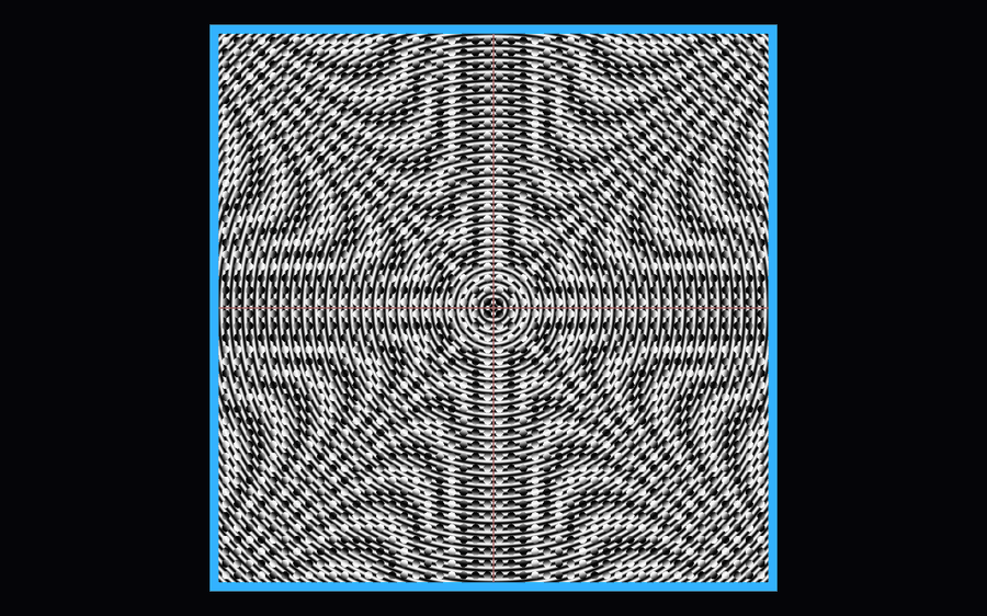
The scene is three parallel planes in millimetres. The bead array sits at z = 0, the observer on the +z side, and the printed image at z = −d behind the beads. The default is 2 mm glass beads in a 48×48 square grid with a 1 mm edge gap, image distance 2 mm, refractive index 1.5. Only square packing is supported; the pitch is bead diameter + gap, so 2 mm beads with a 1 mm gap sit on a 3 mm pitch. That one choice sets the void fraction: touching beads leave ≈21.5% gaps, the default layout ≈65%. Light that misses a bead does not bend — it passes straight through to the print.
Each bead is a ball lens whose focal length, measured from the sphere centre, is f = nR/(2(n−1)). For R = 1 mm and n = 1.5 that is 1.5 mm. With the image 2 mm behind the array, the lens works just beyond its focal plane — the regime that produces the effect instead of a clean inverted image.
Thin lens or Snell’s law: two models of the same bead
Mode A, ideal lens, treats each bead as a paraxial thin lens at z = 0 with aperture R. A ray crossing at transverse height h is deflected by α' = α − h/f and continues to the image plane. No spherical aberration, no total internal reflection, cheap to evaluate, good enough for geometric intuition.
Mode B, refraction, does the honest thing: intersect the front sphere by solving t² + 2(u·(O−C))t + |O−C|² − R² = 0 and taking the near root, refract each surface with Snell’s law n₁ sin θ₁ = n₂ sin θ₂, exit a hemisphere through its flat back at z = 0, or refract twice through a full sphere. When a ray hits at too steep an angle, total internal reflection reflects it and the shader tries the next exit surface, up to a fixed bounce cap (four by default).
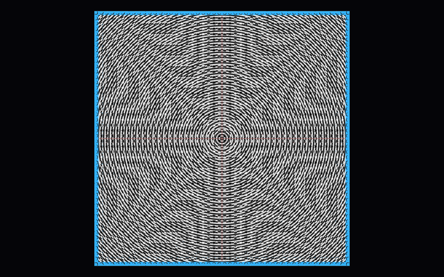
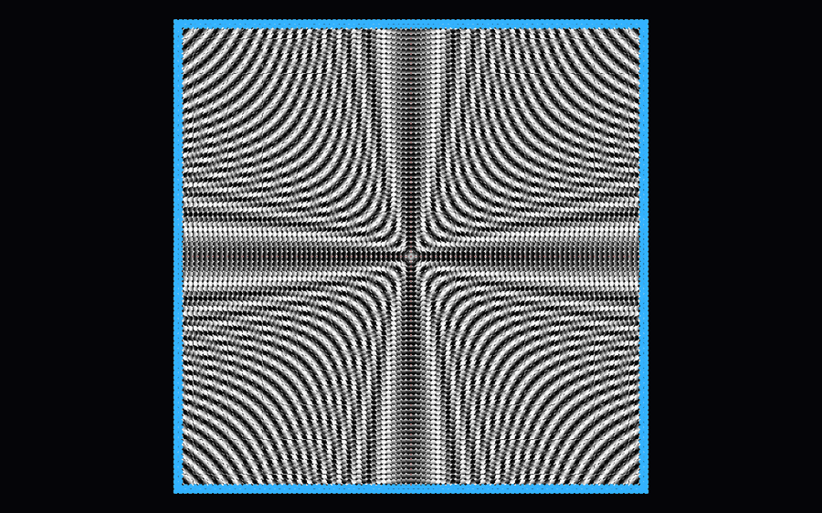
Mode A is the paraxial limit of mode B. In the renders they share a layout but not a texture: real refraction tightens the centre vortex, darkens the edges where rays are lost to TIR, and shifts where the bright and dark bands fall.
Why you see moiré magnification and not the photo
Under a pinhole camera, a bead does not see the whole image plane. It samples a window about
span = 2R · |1 − d/f|wide and magnifies it by
|M| = f / (d − f)For the defaults, span ≈ 0.667 mm and |M| = 3. Feed the array a smooth photograph and each bead shows a near-uniform colour patch, because within 0.667 mm a smooth photo has no detail — a mosaic of coloured dots, correct rather than a bug. Feed it a pattern whose period is close to the bead pitch and the two beat: the eye sees a moiré pattern many times larger than either the beads or the rings. This is the same sampling argument behind lenticular and integral-imaging prints — and why good glass-bead art starts from a designed pattern.
Push the image distance toward focus (d = 1.6 mm here) and |M| climbs toward 15, the window shrinks, and the rings dissolve into a denser diamond moiré. Shrink the beads to 1 mm on a 96×96 grid and the pitch itself changes, so the beat frequency changes and the pattern rearranges.
A GPU shader that traces one ray per pixel
The renderer is one fragment shader on a full-screen triangle — three vertices from gl_VertexID, no vertex buffer. For each pixel it builds a primary ray from the camera basis and field of view, finds where it crosses z = 0, and locates its bead with a single floor on the array coordinates. Because the packing is square, the containing cell’s centre is the nearest bead — no neighbourhood search, no acceleration structure.
Then it does the counter-intuitive thing: it traces the ray backward, from the camera, not forward from the print. That is exact, not an approximation, by Helmholtz reciprocity — with no absorption and no multiple reflections, “camera to image” and “image to camera” give the same picture. The payoff is enormous: instead of radiating from every image pixel across a hemisphere and waiting to see which rays reach the lens, I trace only the rays that enter the camera.
The CPU mirrors the shader deliberately: optics.py is a pure-function version of the same formulas, lattice.py builds the identical grid, and unit tests assert the two agree. Keeping one numerical truth in two implementations is the same discipline I described in how to read a codebase you didn’t write.
The engineering that made it real-time
A correct shader is not a usable program.
The Qt plus moderngl context trap. The obvious design — draw into a QOpenGLWidget with a moderngl context bound to it — crashes on X11. The first moderngl.create_context(standalone=False) binds the current Qt context and caches it; the second call finds a non-empty cache and runs in mode="detect", creating a second context. Two contexts contending for one GLX drawable is BadAccess and a segfault. The fix is to never touch Qt’s GL context: create one standalone context, render to an offscreen framebuffer, read pixels back into a NumPy array, and hand that to an ordinary QWidget as a QImage. Multiple views share the single context, on Wayland and xcb alike.
Cache the lattice. Early on the scene rebuilt its bead-centre array every frame — about 19 ms per frame for a 128×128 array. Caching it and rebuilding only when (cols, rows, diameter, spacing) changes dropped that to 0.012 ms and moved forward rendering from 35 fps to 125 fps.
Render only on change. A dirty flag means an idle window burns zero GPU. While you drag, supersampling drops to 1×; on release it returns to the set factor. Supersampling happens on the GPU — render large, scale down in a second pass, read back only the target size — so the expensive readback stays constant. That is ~59.5 fps dragging at 1345×920 and 44 fps idle at 2×. Raw throughput at 1280×800 is far higher: ~1011 fps ideal, 615 fps hemisphere refraction, and 603 fps for a full sphere.
Inverse design: printing a 3D model behind the beads
Forward simulation tells you what a given print looks like; the more useful question is the reverse — what do I print so that a 3D model appears? One neat identity answers it. Set the sampled window to one N-th of the pitch, span = pitch / N, and substitute the span formula:
d = f · (1 + 1/N) and |M| = NAt that image distance each bead displays exactly one sub-cell of the canvas, magnified N times. Render the model from N×N slightly different directions, interleave those images into one canvas by taking every N-th pixel, place it at distance d, and each bead picks the sub-cell matching the current view direction. Move your head and every bead flips to its neighbour; the array switches viewpoint together, and that parallax reads as depth. Empirically N = 15 looks best; 3, 5, and 7 are visibly choppier because the viewpoints are further apart. The honest constraint is that spatial resolution equals bead count — one sample per bead — so the demo uses 0.8 mm beads on a 128×128 grid, and 48×48 looks coarse.
What it does not model
I would rather state the gaps than let a slick render imply more than it proves.
- One refractive index, no dispersion. All colour channels share a single n, so there is no chromatic aberration and no rainbow in the highlights — both of which real glass beads show.
- A pinhole camera, no depth of field. Every ray enters through a point, so no out-of-focus planes exist.
- Gap colour fringing is real, not a bug. Light passing between beads hits the extreme-angle sub-cells at the canvas edge and produces thin coloured fringes; that is what a transparent gap physically does. An opaque black substrate looks cleaner but is a different object.
- Discrete-view ghosting. With N viewpoints there are N−1 transitions, and a mid-transition bead blends its neighbours into a faint double image — the same artefact photographic lenticular prints have.
What I took away
DotLens3D pleases me because the physics is small enough to hold in your head and still surprising: a ball lens, one focal-length formula, one sampling window, and a beat frequency between two periodic grids produce an image that looks like it must involve something cleverer. It does not — it is Helmholtz reciprocity, a floor, and a shader run once per pixel.
I also built it the way I like to build tools now: local, offline, and mine. It needs no server; the canvases it generates are yours as files — the same argument I made for local-first software. With a pile of tiny beads and a printer, the inverse-design path now lets you put a model behind them; the rest is three planes of geometry and a well-placed ray.